 Petit Labs
Using Sandy 3.0 Flash Library
Part 5. Materials
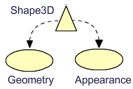
Two main properties of a Shape3D creates the visual experience of 3D objects in Sandy. One is the Geometry which determines the shape of the object, the other is the Material, that determines the color and structure of the objects surfaces. So far we have seen objects with color and lines. If you have studied the Sandy demos, you know that this is only the simplest of appearances of Sandy objects. In this tutorial we will study the different appearances we can give to our objects to make them more interesting.
Start by downloading the sources for this tutorial ( Updated 2007-11-27. )
Introduction
Every shape3D has an Appearance property, which contains materials for the front and back faces of its surfaces. It is possible to use one appearance for the whole object or different appearances for different polygons, making up the object.
You can dress your objects in a variety of materials, from plain colors over static textures to animated materials and video materials. You can make your materials more or less transparent and you can use ambient and reflective light on them.
The Appearance combines different visual aspects of the surface properties in a parent to child relationship.

You create your front material and possibly back material with the material attributes you want. You feed them to a new Appearance and assign it to your object or part of it.
var lineAttr:LineAttributes = new LineAttributes( 0.5, 0xFF0000, 0.4 );
var myMaterial:ColorMaterial = new ColorMaterial( 0x5F0756, 1, lineAttr );
var myAppearance:Appearance = new Appearance( myMaterial, myMaterial );
myBox.appearance = myAppearance;
Here we create an Appearance with a ColorMaterial as front and back
materials. The material has a opaque dark violet color ( alpha = 1 ) with a
LineAttributes.
The LineAttributes gives us edge lines for the polygons, with the thickness
0.5 and a red transparent color ( alpha = 0.4 ).
Finally the object myBox is dressed in the created Appearance. It may seem like a lot of work, but it is really efficient and flexible.
Most of the arguments passed to the constructors are optional. If you only pass a front material to the Appearance constructor, that material will be used as back material as well. You can also pass more MaterialAttributes to the Material constructors, or none at all. We will see more of this, as we start crafting appearances.
I recommend that you have the API documentation ready for consultation when you explore the possibilities. Let's move!
Using color materials
We are going to use the same setup with few changes for all basic material tests, so here is the basic structure of our applications - mostly a repetition of what we have seen earlier. I'm using Flash CS3 IDE here, and set the stage to 200 by 200 pixels.
Here is the document class ( application class ).
We start with some necessary imports.
	import flash.display.Sprite;
	import flash.events.*;
	import flash.display.Stage;
	import flash.ui.Keyboard;
	import sandy.core.World3D;
	import sandy.core.data.Vector;
	import sandy.core.scenegraph.*;
	import sandy.materials.*;
	import sandy.materials.attributes.*;
	import sandy.primitive.*;
Our document class extends Sprite. We also need a few instance variables, accessible from any method of the class.
	public class ColorTest extends Sprite
	{
		private var world:World3D;
		private var camera:Camera3D;
		private var box:Shape3D;
		private var moving:Boolean = false; // Rotate our object?
The constructor sets up the world.
	public function ColorTest()
	{
		world = World3D.getInstance();
		world.container = this;
		world.root = createScene();

		camera = new Camera3D( 200, 200 );
		world.camera = camera;
		camera.z = -200;
		world.root.addChild( camera );

		Key.initialize( stage );
		stage.addEventListener( MouseEvent.MOUSE_DOWN, downHandler );
		stage.addEventListener( MouseEvent.MOUSE_UP, upHandler );
		addEventListener( Event.ENTER_FRAME, enterFrameHandler );
	}
The world is instantiated and "this" Sprite is set as the world container.
The createScene method creates the root group and its content.
The camera is created with a view port the same size as the stage, and added to the root group. Note that the root group must exist, which the createScene method has ensured.
The keyboard listener class is initialized and event listeners for mouse events are added to the stage. Finally we listen for enter frame events for frame based animations.
We have two mouse listeners, just to flag if we should move our object or
not.
Here are the event handlers.
	// Should we move our box or not?
	private function downHandler( e:Event ){
		moving = true;
	}
	private function upHandler( e:Event ){
		moving = false;
	}
Now let's get on with the interesting part, the creation of the scenery!
	// Create the root Group and the object tree
	private function createScene():Group
	{
		var root:Group = new Group();
		box = new Box( 'box', 60, 60, 60, PrimitiveMode.TRI, 2);

		var material:Material = new ColorMaterial( 0xFFCC33 );

		var app:Appearance = new Appearance( material );

		box.appearance = app;
		root.addChild( box );
		return root;
	}
Here we have created a simple ColorMaterial for the front appearance of a
box.
Before we look at the result, lets see what frame based animations we have.
	private function enterFrameHandler( event : Event ) : void
	{
		if ( moving ) {
			box.rotateY += ( mouseX - 100 )/20;
			box.rotateX += ( mouseY - 100 )/20;
		}
		if (Key.isDown(Keyboard.UP)) {
			camera.moveForward( 2 );
		}
		if (Key.isDown(Keyboard.DOWN)) {
			camera.moveForward( -2 );
		}
		world.render();
	}
If the mouse button is pressed, the moving flag is true and we rotate the box around the x and y axes. If one of the UP or DOWN keys on the keyboard is pressed, the camera moves in our out on the object. Finally the world is rendered.
Here it is now.
Setting the alpha value to something between 0 and one, means that the material will be semi transparent, seen to the right above.
Here is the new color material.
var material:Material = new ColorMaterial( 0xFFCC33, 0.6 );
Let's add a MaterialAttributes to get edge lines for all polygons.
	var materialAttr:MaterialAttributes =
		new MaterialAttributes(
		new LineAttributes( 0.5, 0x2111BB, 0.4 ));

	var material:Material = new ColorMaterial( 0xFFCC33, 0.6, materialAttr );
The material attributes contains line attributes with line thickness of 0.5, a color value and an alpha value. The result is shown to the left below.
We can add more material attributes. To the right is an example with a light attribute.
	var materialAttr:MaterialAttributes =
			new MaterialAttributes(
				new LineAttributes( 0.5, 0x2111BB, 0.4 ),
				new LightAttributes( true, 0.1 ));

	var material:Material = new ColorMaterial( 0xFFCC33, 0.6, materialAttr );
	material.lightingEnable = true;
To use light, we have to give the material some light attributes. The first argument to LightAttributes is a boolean flag for the intensity interval to use. If set to true, the interval goes from black to strongest light - if false the intensity can go from black to normal appearance. The second argument is the intensity of ambient light.
We also have to enable light for the material to use it.
If we like to have a special drawing touch to our objects, we can add an outline by using the OutlineAttribute.
	var materialAttr:MaterialAttributes =
			new MaterialAttributes(
				new LineAttributes( 0.5, 0x2111BB, 0.4 ),
				new LightAttributes( true, 0.1 ),
				new OutlineAttributes( 6, 0x2111BB, 0.8 ));
The arguments to OutlineAttributes are thickness, color and alpha, and here is the neat result. The ActionScript source file ColorTest.as contains the complete appearance.
Two sides of the coin
So far we have looked at dressing up only one side of the cube surfaces, the
front side.
For the Box primitive, this means the outside, or in other words the front
side of every polygon making up the cube.
Maybe you zoomed in near enough to get the cube clipped against the near plane of the camera. If not, I suggest you do that now. At first the inside looks white, but upon further examination you find that the inside doesn't seem to exist at all. Moving the camera inside the cube makes it disappear. Strange behavior you may think.
This is to save calculations and preserve resources, for the cases when we are only interested of the front sides. If we want to allow the user to get inside the cube and still have it visible, there are a few things we can do. The obvious way, is to set a back material, but I'll get back to that in just a moment.
First we should see if we can do with just the front material. I said so in
the introduction, which you have now forgotten :)
If that is true, why don't we see the front material inside the cube? Well
another smart move by the library developer, is to use back face culling,
again to save resources.
Back face culling means that normally hidden surfaces are by default not drawn. We can change this by explicitly disabling back face culling.
box.enableBackFaceCulling = false;
The enableBackFaceCulling is a property of Shape3D. Here we are.
Except for disabling back face culling, I have disabled the use of light and set the alpha value of the ColorMaterial to 1, that is opaque. This is just to get a nicer impression. Using the Up/Down navigation keys, we can get inside the cube and see that the front material is in fact used even for the back side.
Another trick we can do, if we only want the user to see the inside, is to swap which side of the polygons should be culled. If we know that the user will always be inside the cube, there is no need to draw the outside. Let's look at that possibility too.
	//box.enableBackFaceCulling = false;
	box.swapCulling();
With back face culling on ( the default ) and after swapping the culling side for each polygon, only the inside should be visible. To make the experience better when inside the cube, I have pumped up the quality of the cube to 4.
As you can see the outside of the cube surfaces are gone, but if you move the camera inside the cube, you can rotate around and look at all inside surfaces. This of course is only useful if you keep your user inside at all times :)
Finally, let's use different materials on the inside and the outside. Here is the pertinent part of the createScene method.
	var materialAttr:MaterialAttributes =
			new MaterialAttributes(
				new LineAttributes( 0.5, 0x2111BB, 0.4 ));

	var frontMaterial:Material= new ColorMaterial( 0xFFCC33, 1, materialAttr );
	var backMaterial:Material = new ColorMaterial( 0xB1E3EF, 1, materialAttr );
	var app:Appearance = new Appearance( frontMaterial, backMaterial );
	box.appearance = app;
	box.enableBackFaceCulling = false;
We still have to have the back face culling disabled to see anything on the inside. To simplify, I don't have any light attributes in this case. When we zoom into the cube or rotate inside it, the polygons ( triangles ) suddenly disappear and return. This happens when at the near plane of the camera. This is due to yet another way of saving computational resources.
When the object comes near the camera and intersects what is called the near plane, it should be clipped. This should be done by clipping the intersecting polygon and calculating new vertices for the clipped polygon. Here the intersecting polygon is culled ( not shown ) which is a very rough way of clipping the object. Of course we can fix this in the versatile Sandy library.
We just have to set the property enableNearClipping to true, and the clipping is nice and smooth, as we can see in the right example above. Add this line:
box.enableNearClipping = true;
Next we'll visit the more interesting BitmapMaterial and get some texture on our objects.